#2.1.1
Standard circuit diagram symbols
Circuit diagrams use standard symbols.
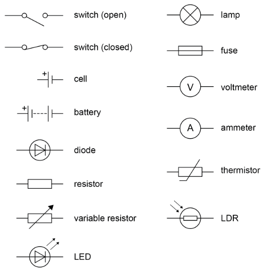
Students should be able to draw and interpret circuit diagrams.
#2.1.2
Electrical charge and current
For electrical charge to flow through a closed circuit the circuit must include a source of potential difference.
Electric current is a flow of electrical charge. The size of the electric current is the rate of flow of electrical charge. Charge flow, current and time are linked by the equation:
\(\text{charge flow} = \text{current} × \text{time}\)
\(Q = It \)
charge flow, Q, in coulombs, C
current, I, in amperes, A (amp is acceptable for ampere)
time, t, in seconds, s
A current has the same value at any point in a single closed loop.
#2.1.3
Current, resistance and potential difference
The current (I) through a component depends on both the resistance (R) of the component and the potential difference (V) across the component. The greater the resistance of the component the smaller the current for a given potential difference (pd) across the component.
Questions will be set using the term potential difference. Students will gain credit for the correct use of either potential difference or voltage.
Current, potential difference or resistance can be calculated using the equation:
\(\text{potential difference} = \text{current} × \text{resistance}\)
\(V = IR \)
potential difference, V, in volts, V
current, I, in amperes, A (amp is acceptable for ampere)
resistance, R, in ohms, Ω
#2.1.4
Resistors
Students should be able to explain that, for some resistors, the value of R remains constant but that in others it can change as the current changes.
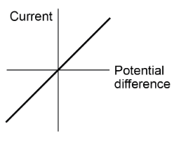
The current through an ohmic conductor (at a constant temperature) is directly proportional to the potential difference across the resistor. This means that the resistance remains constant as the current changes.
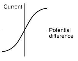
The resistance of components such as lamps, diodes, thermistors and LDRs is not constant; it changes with the current through the component.
The resistance of a filament lamp increases as the temperature of the filament increases.
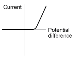
The current through a diode flows in one direction only. The diode has a very high resistance in the reverse direction.
The resistance of a thermistor decreases as the temperature increases.
The applications of thermistors in circuits eg a thermostat is required.
The resistance of an LDR decreases as light intensity increases.
The application of LDRs in circuits eg switching lights on when it gets dark is required.
Students should be able to:
- explain the design and use of a circuit to measure the resistance of a component by measuring the current through, and potential difference across, the component
- draw an appropriate circuit diagram using correct circuit symbols.
Students should be able to use graphs to explore whether circuit elements are linear or non-linear and relate the curves produced to their function and properties.